


-
About us
- Products
- Services
- Contact
=O=
Turbo Cleaner CTY-2002
Prospect ~ 0.09 MBDownload
1. Introduction to top
The APSON Turbo Cleaner CTY-2002 is a pneumatically controllable
rinsing block for aggressive lacquers and solvents. It is an optionally
available cleaner block for the modular APSON Lacquer Changer ###-2000 M
and is particularly suitable for automatic painting systems with often
changing lacquers. It serves for rinsing the lacquer change-over switch,
the hoses and rotation atomizers or spray guns.
APSON Turbo Cleaner CTY-2002
The APSON Turbo Cleaner CTY-2002 is an advancement of the APSON
Pulse Cleaner ### and APSON Turbo-Pulse Cleaner ###. It differs from the
aforementioned cleaners by more flexible rinsing sequence due to
non-coupled function of the valves. In all other respects the cleaners
mentioned are exchangeable. The APSON Turbo Cleaner CTY-2002 is optimized
for economical solvent consumption with high rinsing quality. It avoids
reliably a pollution of the newly connected lacquer during the painting
process and ensures thus a perfect lacquer change.
2. Features to top
-
Small solvent consumption.
-
Environmental careful short rinsing cycle due to high throughput.
-
Very good rinsing barness due to deathroom-minimized valve blocks.
-
The valves are compatible with the valves of the lacquer change-over switch blocks.
-
Fast valve exchange due to screwable valve technique.
-
Pro-active maintenance possible due to leakage display of the valves.
-
Visible switching status of the valves.
-
Small, compact form.
3. Structure and Function to top
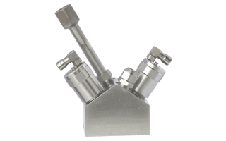
The APSON Turbo Cleaner CTY-2002 consists of a prism formed housing
with an output and one input each for solvent LO and compressed air LU.
The output side of the Turbo Cleaner CTY-2002 forms a pressure tight
interface to the valve blocks of the lacquer changer switch.
APSON Turbo Cleaner CTY-2002
A pneumatically controllable valve is assigned to each input. Due to
the special formation of the eddy space and the V-shaped arrangement of
the valves, a highly turbulent mixture of air and solvent develops in the
lacquer change-over switch during the rinsing cycle.
Due to the special construction the APSON Turbo Cleaner CTY-2002
enables two basic application cases:
-
Application with alternating control of the valves for air resp. solvent.
-
Application with permanent control for air and pulsed control of the solvent.
Case 1: Application with
alternating control of the valves for air resp. solvent. In this case both
inputs are to be equipped with checkvalves, in order to prevent
penetration of the different medium during possible overlap of the
open-times (both valves at the same time openly) in each case.
During the painting process solvent and compressed air pend
permanently at the turbo cleaner. If a rinsing cycle is to be initiated,
then with still closed compressed air valve LUF first the solvent valve
LOF is controlled to open. Briefly afterwards, the compressed air valve is
controlled to open for the entire duration of the rinsing cycle. With
opened compressed air valve the flow of the solvent is then periodically
interrupted in short time intervals and released again. At the end of the
rinsing cycle the air flow as well as the solvent flow are stopped.
Due to this sequence an alternating flow from
compressed air resp. solvent develops, which rinses reliably the lacquer
change-over switch downstream the hoses and other spray devices. The
duration of the rinsing cycle as well as the switching sequences of the
two valves depend on the conditions of the painting process and has to be
controlled by means of a programmable logic controller. The more briefly
the switching on impulses of the solvent valve (preferably smaller than
1 second), the better the rinsing quality.
Case 2: Application with
permanent control for air and pulsed control of the solvent. For safe
functioning of the Turbo Cleaner 2002 the pressure at the solvent input
must be higher approx. 1 to 1.5 bar than the pressure at the compressed
air input. Therefore only the union fitting for the compressed air input
contains a checkvalve.
During the painting process solvent and compressed air pend
permanently at the Turbo Cleaner 2002. If a rinsing cycle is to be
initiated, then with still closed compressed air valve LUF first the
solvent valve LOF is controlled to open. Briefly afterwards, the
compressed air valve is controlled to open for the entire duration of the
rinsing cycle. With opened compressed air valve the flow of the solvent is
then interrupted in short time intervals and released again. At the end of
the rinsing cycle the air flow as well as the solvent flow are
stopped.
Due to this sequence a pulsating flow from
air-sputtered solvent develops, wich rinses reliably the lacquer
change-over switch downstream the hoses and other spray devices. The
duration of the rinsing cycle as well as the switching frequency of the
solvent valve depend on the conditions of the painting process and has to
be controlled by means of a programmable logic controller. The more
briefly the switching-on impulses of the solvent valve (preferably smaller
than 1 second), the better the rinsing quality.
4. Technical Data to top
| Denomination: | APSON Turbo Cleaner CTY-2002 |
|---|---|
| Media: | Lacquers, solvents, a.o. |
| Compressed air pressure: | 6 to 12 bar |
| Solvent pressure: |
(approx. 1 to 1.5 bar greater than compressed
air)
|
| Valve assembly: | two 2/2-ways valves, see Ordering Data |
| Checkvalve/s: | 1 resp. 2 checkvalve/s, see above |
| Valve switching pressure: | 6 to 8 bar, measured at the valve |
| Housing material: | Inoxidable steel, see Ordering Data |
| Sealing material: | Viton™, or after customer's request |
| Control air link: | for hose, d = 2.7 mm, D = 4 mm |
| Compressed air input: | for hose, d = 8 mm, D = 10 mm |
| Solvent input: | for hose, d = 6 mm, D = 8 mm |
| Dimensions, block: | length 70 mm, depth 42 mm, height 50 mm |
| Dimensions, complete: | length 70 mm, depht 42 mm, height 87 mm resp. 110 mm |
| Mass, block: | approx. 700 g |
| Mass, complete: | approx. 800 g |
5. Ordering Data to top
| Denomination | Quantity | Part-Nr. |
|---|---|---|
| APSON Turbo Cleaner CTY-2002, complete | 1 | 070-A004 |
| APSON 2/2-Ways Valve 2000 | 2 | 060-A008 |
| APSON Checkvalve 2000 | 1 bzw. 2 | 100-A001 |
Options:
-
Housing from aluminium, anodized.
-
Sealing material, after customer's request.
-
Air/solvent links, after customer's request.